Cable tray load capacity and support spacing are critical considerations when designing electrical cable management systems for industrial facilities, commercial buildings, warehouses and infrastructure projects in Saudi Arabia. Selecting the correct tray is only part of the process. The tray must also support the combined cable load across the planned support spans without exceeding its rated capacity.
For electrical engineers, contractors and procurement teams, understanding these requirements helps prevent excessive deflection, installation problems and costly changes during construction. The correct design depends on the tray type, material, dimensions, cable weight, support arrangement and manufacturer specifications.
This guide explains how cable tray load capacity is evaluated, how support spacing affects performance and what project teams should check before specifying a cable tray system in Saudi Arabia.
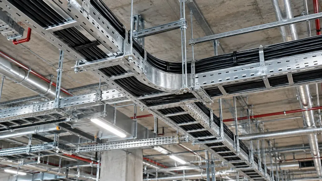
What Is Cable Tray Load Capacity?
Cable tray load capacity is the amount of load a tray can safely support under specified installation conditions. It is commonly expressed as a uniformly distributed load over a defined span, although the exact rating method depends on the manufacturer's documentation and applicable design requirements.
The total load includes the weight of the installed cables and any additional loads permitted by the tray design. The tray's own weight is also relevant to the overall structural design of the supporting system.
A tray with a high load rating at one support span may have a lower rating when installed across a longer span. For this reason, a load capacity figure should never be considered separately from the support spacing and installation configuration for which it was established.
Engineers should use the manufacturer's published load tables for the exact tray model, material, width, side rail height and support span being considered.
Why Support Spacing Matters
Support spacing is the distance between adjacent points where the cable tray is supported by brackets, hangers, frames or other approved structural arrangements.
When support points are placed farther apart, the tray generally experiences greater bending and deflection under the same load. Shorter spans can reduce bending, but they may require additional brackets, structural attachments and installation work.
The appropriate spacing depends on the tray's construction, material thickness, dimensions, cable load and rated performance. It may also be influenced by the location of joints, bends, tees, vertical sections and other fittings.
For example, a tray system installed in a factory may need a different support arrangement from one installed above a suspended ceiling. The final design should follow the manufacturer's installation instructions and the approved project drawings rather than a single assumed spacing value.
Factors That Affect Cable Tray Load Capacity
Several factors determine whether a cable tray is suitable for a particular electrical installation.
Tray Type and Construction
Ladder, perforated, solid bottom and wire mesh cable trays have different structural characteristics. Their load performance depends on the design of the side rails, cross members, base, wire construction and connections.
A ladder tray may be appropriate for certain heavy cable installations, while wire mesh trays are often used for data and communication cabling. However, the tray type alone does not establish its capacity. The exact product rating must be verified.
Tray Width and Side Rail Height
Width and side rail height influence the tray's geometry and its ability to accommodate the planned cables. A wider tray may allow more cables to be installed, but this also increases the potential load.
A deeper side rail does not automatically mean that every tray configuration can support a particular load. Performance must be assessed using the manufacturer's rating for the complete configuration.
Cable Weight and Arrangement
The number, diameter and weight of cables affect the load imposed on the tray. Power cables can be substantially heavier than many control or communication cables, so cable quantity alone is not a reliable measure of loading.
Engineers should calculate the expected cable load from the cable schedule and consider future additions where the project design requires expansion capacity.
Cable arrangement also matters. The design must follow applicable requirements for cable spacing, grouping, segregation and heat dissipation.
Material and Environmental Conditions
Steel trays, galvanized finishes and other material options may be suitable for different installation environments. Corrosion exposure, temperature, moisture and outdoor conditions should be considered when selecting the tray and its protective finish.
The selected material and finish must meet the project's environmental and service life requirements. A corrosion resistant finish does not replace the need to verify structural capacity.
How to Determine the Required Support Span
Selecting a suitable support span begins with the actual cable load and the manufacturer's load data.
First, identify the tray model and configuration. Confirm its width, side rail height, material, finish and any relevant product ratings.
Next, calculate the expected cable load using the cable schedule and manufacturer data. Include the planned cable arrangement and any additional loads specifically permitted by the tray manufacturer.
Then review the manufacturer's load tables or engineering documentation to identify the permitted support spans for the required loading conditions. Check the specified deflection limits and any restrictions relating to joints, cantilever supports or fittings.
Finally, coordinate the support arrangement with the building structure and approved drawings. The brackets, anchors, threaded rods and supporting steelwork must also be suitable for the loads they will carry.
If the proposed arrangement falls outside the published ratings, obtain an approved engineering assessment or select a configuration with appropriate documented capacity.
Cable Tray Load Capacity for Different Applications
The required tray configuration varies according to the installation.
In industrial facilities, cable trays may carry power cables, control wiring and instrumentation cables across production areas. The design should account for the combined cable load, operating conditions and maintenance requirements.
In commercial buildings, trays may be installed above ceilings, in service corridors or inside electrical rooms. Space limitations, access for maintenance and coordination with other building services can influence the support arrangement.
Data centres and communication installations may use wire mesh trays to organize network and communication cables. Cable quantity, future expansion, routing and the manufacturer's load rating remain important considerations.
Outdoor installations require particular attention to the environment, structural supports and protective finish. Wind exposure and other external loads should be evaluated where they apply to the installation design.
In every case, the cable tray system should be selected for the actual application rather than relying on a general load capacity figure.
Common Cable Tray Support Design Mistakes
One frequent mistake is selecting a tray based only on its width. A tray may have enough space for the cables but still be unsuitable for their combined weight or the proposed support span.
Another problem is applying the same support spacing to different tray models. Tray construction and manufacturer ratings vary, so a spacing suitable for one product cannot automatically be used for another.
Ignoring the weight of accessories and failing to coordinate support locations with fittings can also cause problems during installation. Unplanned cable additions may increase the load beyond the original design assumptions.
Project teams should avoid relying on generic online load figures without checking the exact product documentation. They should also verify that the supporting structure and its connections are suitable for the intended installation.
What to Check Before Ordering Cable Trays in Saudi Arabia
Before requesting a quotation, prepare the cable schedule, installation drawings and required tray specifications. Identify the tray type, width, side rail height, material, surface finish, total route length and required fittings.
Provide the expected cable loading and proposed support span when this information is available. Include environmental conditions, project standards and any required technical submittals.
Ask the supplier for the relevant product data, load tables and installation guidance. If the project requires calculations or compliance documentation, confirm these requirements before finalizing the purchase.
For projects in Riyadh, Jeddah, Dammam and other Saudi Arabian locations, the specification should reflect the actual installation environment and project requirements. Location alone does not determine the correct tray rating or support spacing.
Choosing a Cable Tray System for Your Project
A reliable cable tray design combines suitable product dimensions, verified load capacity, appropriate support spacing and a compatible installation environment. Reviewing these factors before procurement helps project teams reduce design changes and make better informed purchasing decisions.
Hitech Fence supports customers exploring cable management and related industrial solutions in Saudi Arabia. When comparing options, evaluate the tray specifications against the cable schedule, approved drawings and installation requirements.
For a project specific recommendation, share the required tray configuration, cable loading, proposed support span and project documentation when requesting a quotation. These details help establish which available configuration is suitable for further technical evaluation.
Frequently Asked Questions
Load capacity depends on the tray design, material, dimensions, support span and manufacturer's published ratings. The weight and arrangement of the installed cables must also be considered.
There is no single spacing suitable for every cable tray. The required span depends on the exact tray model, expected load, allowable deflection and manufacturer's installation requirements.
Increasing the span may reduce the number of supports, but it can also increase deflection and structural stress. Any change must remain within the manufacturer's rated limits and the approved engineering design.
Width influences the tray configuration and the amount of cable it can accommodate. However, capacity depends on the complete tray design and support arrangement, not width alone.
Request the applicable product specifications, dimensional drawings, load tables, installation instructions and any project specific compliance documents required by the approved specification.