Cable tray earthing and bonding are important parts of electrical installation design in industrial facilities, commercial buildings, warehouses and infrastructure projects across Saudi Arabia. Metallic cable trays can provide a conductive path, but their electrical continuity and connection to the earthing system must be properly evaluated to support safe operation.
For electrical engineers, consultants and contractors, selecting a suitable cable tray is only one part of the installation. They must also consider electrical bonding, fault current paths, connection points, corrosion protection and the requirements of the applicable project standards.
This guide explains the difference between earthing and bonding, why they matter in cable tray installations and what project teams should verify before approving a system.
What Is Cable Tray Earthing?
Earthing connects relevant conductive parts of an electrical installation to the designated earthing system. Its purpose is to help maintain safe electrical conditions and provide an appropriate path for fault current, according to the system design.
Metallic cable trays may form part of the installation's protective bonding arrangement. However, a cable tray should not automatically be treated as an equipment grounding conductor. Its use for that purpose must be permitted by the applicable standards and supported by the manufacturer's technical documentation and engineering design.
The earthing arrangement should be determined by a qualified electrical designer based on the electrical distribution system, protective devices, fault conditions and project requirements.
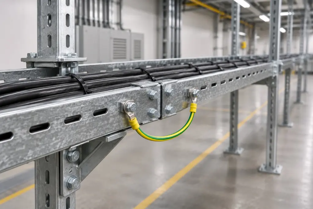
What Is Cable Tray Bonding?
Bonding establishes electrical continuity between conductive components so that they remain at an appropriate electrical potential.
In a cable tray installation, bonding may be required between adjacent tray sections, fittings, covers and other conductive components. The objective is to maintain continuity across the complete arrangement where required by the electrical design.
Connections must be suitable for the expected electrical and environmental conditions. Mechanical contact alone should not be assumed to provide reliable electrical continuity, particularly where coatings, corrosion, loose fasteners or incompatible materials are present.
Difference Between Earthing and Bonding
Although the terms are closely related, earthing and bonding perform different functions. Earthing connects designated parts of the electrical installation to the earthing system. Bonding connects conductive components to maintain electrical continuity and reduce potentially dangerous voltage differences between them.
In a cable tray installation, bonding may connect separate metallic tray sections and associated fittings. The overall bonding arrangement must then be coordinated with the building or facility earthing system.
Both functions should be addressed in the approved electrical design. Installing a bonding jumper does not, by itself, establish that the complete cable tray system has been correctly earthed.
Why Earthing and Bonding Matter in Cable Tray Systems
A metallic cable tray can extend across large areas of a building or industrial facility. Without an appropriate continuity arrangement, separate sections may not maintain the electrical connection required by the design. Correct bonding helps maintain electrical continuity between connected components. It can also help reduce dangerous potential differences during certain electrical fault conditions.
Earthing and bonding arrangements must work with the installation's protective devices. The fault protection design should ensure that an electrical fault can be detected and cleared within the required conditions. For this reason, cable tray earthing should not be treated as a minor accessory decision. It requires coordination between the tray design, electrical protection system and installation method.
Important Cable Tray Bonding Requirements
The required bonding arrangement depends on the cable tray construction, connection details, project standards and installation environment.
Continuity Between Tray Sections
Cable tray sections are often connected using couplers, splice plates or other manufacturer approved fittings. Engineers should verify whether these connections provide the electrical continuity required by the project. Where continuity cannot be established through the mechanical connection, an appropriately specified bonding jumper may be required.
Bonding Across Expansion Joints
Some cable tray systems include expansion joints to accommodate movement caused by temperature changes or structural conditions. Because these joints may interrupt electrical continuity, the bonding arrangement must be designed to maintain the required connection while allowing the intended movement.
The jumper and connection method should be suitable for the specific expansion joint and installation conditions.
Painted and Coated Surfaces
Protective finishes help prevent corrosion, but coatings can affect electrical contact at connection points. Engineers and installers should follow the manufacturer's approved connection details. They should not remove protective coatings or expose bare metal without an approved procedure that addresses both electrical continuity and corrosion protection.
Connections at Bends and Fittings
Bends, tees, reducers and other fittings introduce additional connection points into a tray route. Their bonding requirements should be considered as part of the complete system rather than addressed only along straight sections. The selected fittings and connection accessories should be compatible with the tray model and the approved bonding design.
Selecting Cable Tray Materials for Earthing and Bonding
Material selection influences the electrical and environmental performance of the tray system. Galvanized steel cable trays are widely considered for industrial and commercial installations. Their suitability depends on the product construction, coating specification, connection details and environmental exposure.
Stainless steel trays may be selected for particular corrosive environments, but the grade and connection components must be assessed carefully. Stainless steel does not eliminate the need for a properly designed bonding arrangement.
Aluminum trays have different electrical and mechanical properties from steel systems. Connections between aluminum and dissimilar metals require consideration of material compatibility and galvanic corrosion. Whatever material is selected, the tray, fittings, bonding accessories and supporting components should be evaluated as a compatible system.
Cable Tray Earthing in Saudi Arabian Projects
Electrical installations across Saudi Arabia operate in different environments, from commercial buildings and indoor electrical rooms to coastal facilities and industrial sites. In coastal locations such as Jeddah and Dammam, moisture and airborne salts can contribute to corrosion. This may affect exposed connections and bonding components over time.
Industrial facilities may also involve dust, chemicals, vibration and elevated temperatures. These conditions should be considered when selecting connection materials and planning inspection arrangements.
Project teams should identify the applicable Saudi Building Code requirements, relevant IEC standards, client specifications and any requirements imposed by the project authority or utility. The exact requirements depend on the installation and must be confirmed by the responsible electrical designer. A general cable tray recommendation should never replace a project specific electrical design or an approved technical submittal.
Inspection and Maintenance of Cable Tray Bonding
Inspection helps identify conditions that could affect the intended electrical continuity of a cable tray system.
Maintenance teams should check accessible connections for looseness, corrosion, physical damage and signs of deterioration. Expansion joints, flexible connections and other locations where continuity may be interrupted deserve particular attention.
Where required by the project inspection plan, electrical continuity measurements should be carried out using an appropriate test method and suitable equipment. Results should be evaluated against the applicable acceptance criteria.
If a connection is repaired or replaced, the work should follow the manufacturer's instructions and approved electrical procedures. Protective coatings should also be restored where necessary using a compatible method. Inspection frequency should reflect the installation environment, operating conditions and maintenance requirements rather than relying on one schedule for every facility.
Common Mistakes in Cable Tray Earthing
One common mistake is assuming that mechanically connecting two tray sections always guarantees electrical continuity. The actual connection design and condition must be verified. Another is treating the metallic tray as a replacement for a protective conductor without confirming that this use is permitted by the applicable standards and supported by the product documentation.
Ignoring expansion joints, painted connections and corrosion exposure can also create problems. Similarly, using incompatible bonding components may affect both electrical continuity and long term durability. The most reliable approach is to include earthing and bonding requirements in the design and procurement documentation before installation begins.
What to Confirm Before Procuring Cable Tray Systems
Before ordering cable trays for a project, provide the supplier with the required tray type, dimensions, material, surface finish and installation environment. Where earthing and bonding accessories are required, identify the tray connection design, bonding details and relevant technical specifications. Include approved drawings and the applicable project standards so that product compatibility can be reviewed.
Ask for product documentation covering connection arrangements and any electrical continuity claims relevant to the proposed system. Confirm whether bonding accessories are included in the quotation or need to be specified separately. This helps engineers and procurement teams evaluate the proposed cable tray arrangement before materials are delivered to site.
Selecting a Suitable Cable Tray System
Cable tray earthing and bonding should be considered alongside tray dimensions, load capacity, material selection and installation requirements. A properly coordinated design helps maintain electrical continuity and supports the protective measures specified for the facility.
Hitech Fence provides cable management solutions for customers evaluating industrial and infrastructure requirements in Saudi Arabia. Project teams should review the proposed tray specifications, fittings and connection details against their approved electrical drawings before procurement.
For a project specific enquiry, share the required tray configuration, material, installation conditions and technical specifications. This information helps establish the appropriate product requirements for further review.